
IRF540N · N-Channel MOSFET 100V 33A
IRF540N (N-Channel MOSFET 100V 33A from Infineon) comes in a TO-220 package. Reference unit price: Request quote, minimum order 1 piece. Availability: In stock. Shenzhen Kewei Technology Co., Ltd. supplies this part from Huaqiangbei, Shenzhen, with tiered pricing, small-batch support and full BOM kitting. Prices and lead times are confirmed on inquiry.
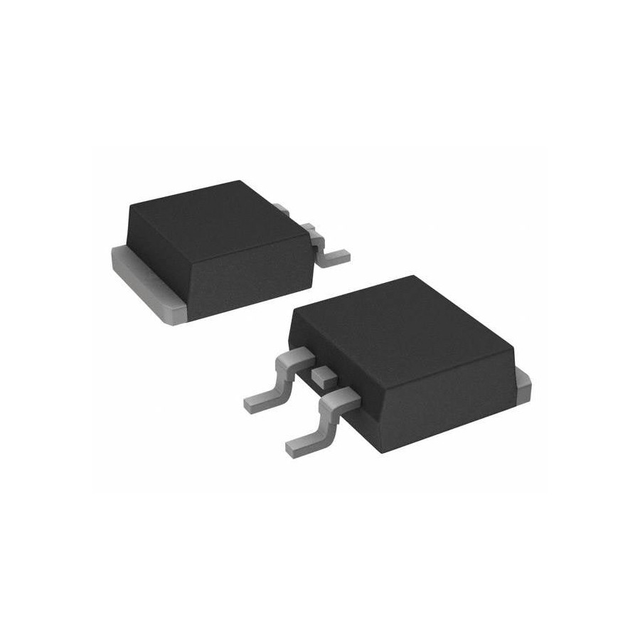
| Part number | IRF540N |
| Manufacturer | Infineon |
| Description | N-Channel MOSFET 100V 33A |
| Package | TO-220 |
| Category | Diodes & Transistors / MOSFETs |
| Reference price | Request quote |
| Min. order | 1 pcs |
| Availability | In stock |
| Reference stock | 2,652 pcs |
IRF540N price and stock (reference)
No tiered pricing is published for this part — please quote by quantity.
IRF540N specifications
| Drain-Source Voltage | 100V |
| Continuous Current | 33A |
| On-Resistance | 44mΩ @10V |
| Gate Charge | 71nC |
| RoHS | Compliant |
About the N-Channel MOSFET 100V 33A
IRF540N is an Infineon N-channel MOSFET in a TO-220 package, listed at 100 V drain-source voltage, 33 A continuous current, 44 mΩ on-resistance at 10 V gate drive and 71 nC gate charge. Calculate conduction and switching loss using the actual gate-drive voltage, load current, switching frequency and heat sink; the 100 V/33 A headline ratings do not apply unchanged to low-voltage gate drive or any thermal design.
The listed values belong together: 100V drain-source voltage, 33A continuous current, 44mΩ specifically at 10V gate drive and 71nC gate charge. Comparing only voltage and current misses gate drive, switching loss and thermal design.
The 10V on-resistance cannot simply be scaled to a 3.3V or 5V gate. Check threshold, output curves, gate charge and temperature conditions in the manufacturer datasheet, then confirm that the driver meets the required switching speed and loss budget.
A TO-220 package does not make 33A automatic. Conduction loss, switching loss, package thermal resistance, heatsinking, ambient temperature and current sharing all affect junction temperature. Pulses and fault conditions also require a safe-operating-area check.
A substitute with similar voltage and current still needs comparison of input capacitance, gate charge, body diode, threshold, thermal resistance and package parasitics. Motor, power and inverter circuits must be checked under the real drive and load conditions.
- Confirm the actual gate-drive voltage and use the corresponding on-resistance and output curves.
- Compare gate charge, input capacitance, switching frequency and driver capability.
- Calculate junction temperature from conduction loss, switching loss, thermal resistance and heatsinking.
- Check safe operating area, body diode, package, pinout and circuit stress.
IRF540N — frequently asked questions
That cannot be concluded from the listing. It gives 44mΩ at 10V and 71nC gate charge but does not identify the part as logic-level. Check threshold, output curves and required drive current in the datasheet.
No. Also compare on-resistance at the intended gate voltage, gate charge, input capacitance, thermal resistance, safe operating area, body diode and package parasitics.
No. The usable current depends on conduction and switching loss, thermal resistance, heatsinking, ambient temperature and switching conditions. Calculate junction temperature at the actual operating point.
Related MOSFETs parts
Genuine parts · small-batch trial runs · full BOM kitting
How to order IRF540N
Send the quantity and the destination country; sales normally responds within two working hours with the unit price, date code, MOQ (1 pcs) and shipping cost. A formal full-BOM quotation normally follows within 24 hours. Shipping is quoted together with the parts.